


Good News for the End of 2020
Leave a CommentFrom: Schroeder Industries’ Fuel Filtration Center of Excellence
New in Bulk Diesel Filtration from Schroeder Industries

The changes of the seasons are upon us all. Fall is setting in the Northern Hemisphere. Spring is in bloom in the Southern Hemisphere. Here is how Schroeder Industries is helping with all of your diesel fuel filtration needs.
Introducing the BDFP and BDFPE from Schroeder Industries
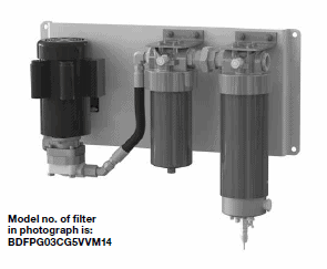
2020 has been a challenging year for so many of individuals. Here at Schroeder Industries, we want to share some good news from our side. Today, we are introducing you to our Bulk Diesel Filtration Panel (BDFP) and our BDFPE (Bulk Diesel Filtration Panel Enclosed).
These Schroeder in-line fuel polishing systems are designed with options from the most basic of operation and integration to hands-free automation and programmable functionality. By using the GHPF, GHCF, BDF2 and BDS products as the foundation for the BDPF and BDFPE, we are able to incorporate that same patented water removal technology and high efficiency particulate filtration of the core components detailed in previous posts and trainings.
These turn-key systems can effectively remove both free and emulsified water as well as solid contamination. This prevents the microbial growth from thriving in the stored fuel.
These systems are competitively priced and outperform all of the competitive products in all categories and performance objectives. By having a better performance with a higher throughput, the Schroeder system can offer the best return on investment.
The BDFP and BDFPE ensure reliable protection of the customers’ installations and equipment. These systems can be “private labeled,” thereby generating new revenue otherwise lost today.
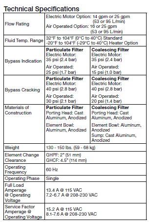
Technical Specifications Shown Below:
How Do They Work?
The BDFP has flow ranges of 14 GPM/ 840 GPH up to 25 GPM /1500 GPH with the electric option. There is an air driven pump option as well at similar flow rates.
This allows for use in applications where electrical service is not readily available. The BDFP is designed for use in basic diesel fuel transfer, polishing and dispensing applications. The BDFP can be used in all three depending on the plumbing configuration.
Example below is for the BDFPE system rated at 15 GPM / 900 GPH.
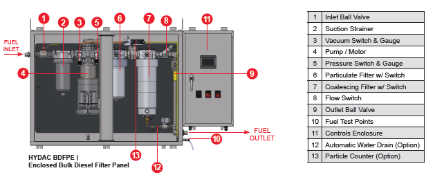
These systems are available at fixed flow ranges from 5 GPM / 300 GPH up to 25 GPM / 1500 GPH. The enclosure configurations from NEMA 12 to NEMA 4X allow the systems to be used for a wide variety of indoor and outdoor installations.
Through regular fuel polishing, the Schroeder BDFPE can protect vital fuel storage, ensuring a reliable supply of clean stable water-free fuel. Additional options and features include external fuel test points, automatic water drain systems, programmable controls, and standard alerts and alarms ensure safe, functional, reliable operation of the fuel polishing system.
An industry innovation incorporates the use of our field-proven particle counting technology to analyze the cleanliness of the fuel in real-time and use that data to automatically adjust run times to meet pre-programmed target cleanliness levels.
The BDFP and BDFPE systems significantly help expand our overall Fuels product offerings with a key focus on Power Generation-Gensets and high flow HP/kW diesel engines.
For more information about Bulk Diesel Filtration, please contact us.
Crazy John’s Filter Factory
Leave a CommentCrazy John’s Filter Factory

As far as it goes, we tell the tale of snow.
The overworked Customer Service
Not ours of course, they keep us afloat.
We sing of jolly snowmen,
And a reindeer with a nose.
That if you look so slightly,
He claims that it glows.
 But deep in the snowy belt,
Lives an elf for whom we don’t talk about.
An elf that wanted nothing more,
Than to be the best filter manufacturer.
Crazy John was his name,
And making Santa filter elements was his game.
One could find, they say,
That Crazy John lived in his Filter Factory.
All through the year, Crazy John worked and worked.
Like a great big ol’ fashion TF1 group.
Crazy John couldn’t stop,
And I’ll tell you why,
It’s because Crazy John knew a guy.
Every year, around the 24th of December,
Crazy John knew it would be a day to remember.
He knew that St. Nicholas would be suspended solid.
Tangled up, sleigh risked being spotted!
So he did what an elf could possibly do.
He worked his fingers through and through.
He knew that if he fit it right,
That perfect Hydraulic filter could keep the sleigh in flight.
But the Saint, himself, could come any day.
The Filter Factory where John slept, worked and play.
So as Crazy John settled down,
A distress call came without a sound.
“John! John!”
The voice did cry,
“I’m test flying
My sleigh
And it
Cannot fly.”
“Oh, John!
Oh, John
He cried
And cried,
“I’ve got to get
To the kids
On Christmas Night.”
Crazy John got up out of kilter,
And worked harder than a Pressure filter.
All came down to a night so dreary,
That behold Santa needed a quick delivery.
“But the filter
Is not ready”
Said John,
And he knew it.
Santa needed a filter for a special type of hydraulic fluid.
The resin was drying, ready for the 25th.
But Santa needed data, no time for a blip.
Crazy John plowed through the snow.
A sight in which he did not know.
And though his bones were a bit shivery,
He set out on a quest to make that day delivery.
Crazy John was parched roughly halfway farther.
But Crazy John forgot his special drinking water.
Nevertheless, it was not the time to distress.
Crazy John’s Filter Element was almost at it’s best.
John had an idea to dry it much quicker.
He’d place it in a Plastic tank in hopes to
Protect it from the bitter.
Alas, he made it to the North Pole, at last.
Now to find St. Nicholas; a challenging task.
Crazy John looked tall scaling every last brick, stone and double wall.
He searched through the ranks;
Searching high and low in Santa’s Storage tanks.
Crazy John popped his head,
In the event that he missed him.
But saw a dark puff,
Black smoke from the hydraulic system.
“Oh John! Oh John!
I’m glad that
You’re here!
We haven’t much time
Christmas is
Almost here!”
Crazy John examined the vessel with care.
And realized the high pressure on the sleigh that stood there.
The Schroeder GZT Crazy John usually worked,
Was not the right solution, no matter how much he twerked.
The presents got heavier as the years went on,
And a typical metal hydraulic tank would not be good for Blitzen or Don.
“There’s not enough
Time for me
To go back.
If only there
Were magic
Still left
In the sack.”
St. Nicholas stopped with a doubt of thank.
He inquired with “Crazy”
About his polyethylene tank.
“What’s that
Crazy contraption
You’ve got there?”
“Why it’s a
TNK7 from
Schroeder Industries,
mon frère.”
“Well, what’s it do,
That tank
You have with you?”
“It’s said to reduce
The weight.
It’s a special
Hydraulic tank.”
It was that moment when a lightbulb went off in Crazy John’s head.
“Santa! That’s It!”
Said John,
In a spit.
“The filters
Not the problem,
It just
Won’t fit!”
So Crazy John pulled out his crazy build on.
He replaced that rusty weighed down Highland.
John retrofitted his tank on top was neither.
That good ol’ GZT and a neat little Air breather.
With a bit of magic and good team building,
St. Nicholas’s sleigh rose up
“For the children!”
Crazy John had a blast on his little vacation,
But starting tomorrow, it was back to
Hydraulic filtration.
Crazy John returned to his Factory alone.
Listened in to hear his silent phone.
Innovation was the reason that saved a good night.
Crazy John began preparing for next year’s flight.
Electric Hydraulic Systems: The Future of Hydraulics
4 CommentsElectric Hydraulic Systems: The Future of Hydraulics

The mobile hydraulics industry is going through a major transformation – moving towards electric hydraulic systems. Electric hydraulic systems hold the potential to be drastically more energy efficient than the typical hydraulic systems that exist today.
To simplify how this is possible, electric hydraulic motor-pump units only operate when flow and pressure are required to perform the working task at hand.
When there is no flow or pressure required, the electric hydraulic motor-pump unit switches to zero energy-mode, saving the consumption of energy and increasing the system’s efficiency. This is what we call Energy efficiency.
Energy efficiency simply refers to the process of reducing one’s system energy. This can be achieved by lowering the amount of energy consumed to accomplish an equivalent output (e.g. halt of use when not in operation).
Think about some of the newer car models in the market today.
Some of the higher-end models shut down every time the car stops at a stop light. Since the car is in idle at that stop light, why would the car continue to place tension and wear the performing components when they’re not performing their sole duty – to drive?
This theology and way of thinking is slowly creeping into hydraulics too. Experts are now looking at ways to incorporate these (and other) types of electric energy to power hydraulic machines.
This is called electric hydraulics.
With the rising trend of electric drive vehicles and utilizing efficient energy throughputs, there is now a need to reduce power consumption and extend the battery life through increased hydraulic efficiency.
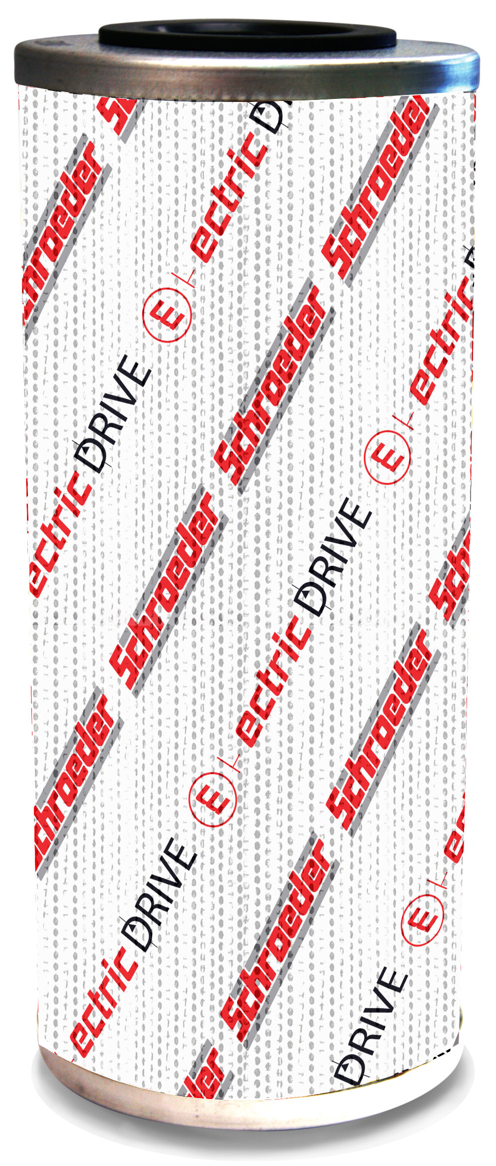
That is where Schroeder’s Electric Drive media can help.

The use of Schroeder’s GREEN, Electric Drive (E-Drive) Media filtration technology guarantees safe and reliable equipment operation, all-while conserving the use of energy.
Part of Schroeder’s Energy Saver initiative, filter elements made using the all-new E-Drive Media are characterized by an unusually low pressure drop, making them suitable for low energy requirements compared to conventional hydraulic elements under the same ambient conditions.
E-Drive Media is the clear choice for use in electric hydraulic drive motor-pump units. Use it for conserving energy bills and wherever high viscosity fluids are employed – especially at low temperatures that produce a cold start behavior.
Schroeder’s E-Drive Energy Saving Features:

- Retains low resistance of flow to reduce the ΔP across the element.
- The filter media construction consists of multi-layered, synthetic fiber material with support.
- Great for cold start conditions where a low pressure drop is required.
Technical Specs:
- Element Collapse Rating: 145 psid (10 bar)
- Temperature Range: -22°F to 212°F (-30°C to 100°C)

- Flow Direction: Outside to Inside
E-Drive Media is currently rated for 8, 10, & 15 µm filtration.
To see if Schroeder’s Energy Saving Initiative E-Drive Media can be the right solution for your electric hydraulic systems, email us at sisales@schroederindustries.com or leave a comment in the blog post below.
Contamination in hydraulic fluid – a myth or reality?
5 CommentsContamination in hydraulic fluid – a myth or reality?

How often have you been told from an asset manager,
“My oil is clean?” Or how about,
“I don’t see any contamination in my oil,” as a bottle of hydraulic oil is held up to light?
You might have even heard other common adages, such as:
“The oil supplier wouldn’t send me dirty oil.”
“I have a filter on the tank to catch the contamination,” later finding out that the filter element has clogged and the filter in bypass, or that the filter element was missing altogether!
“My reservoir is sealed. How did water get in there?”
And the list goes on and on…
Contamination control is an important part of operating and maintaining hydraulic systems.
It starts with the identification and measurement systems of the different forms of contamination. Once a company has identified the contaminants and source of the contaminate, they can develop a strategy for an efficient, real-world method of controlling and maintaining acceptable contamination levels in a hydraulic system.
The result will be improved fluid condition and consequently extend life expectancy of fluid and equipment resulting in significant cost savings.
Types of Contamination
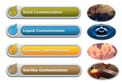
Various types of contamination occur in fluid power systems: solid contaminants, liquid (e.g. water), gaseous (e.g. air) and gel-like contaminants.
Another often-overlooked source for premature fluid degradation and consequent system damage is heat. This is especially important if the tanks size is small and the fluid does not have enough time to properly cool down.
Contamination can cause substantial damage in fluid power systems if they are not removed as quickly as possible. Preventive measures should be taken to reduce the ingress of contaminants in systems.
The contamination that can be most detrimental to a system in operation is one not visible to the naked eye. To put it into perspective, an average healthy human eye can see items down to approximately 40μm (Microns) in size. In comparison, a human hair is 70 to 80μm in size.
Particles that cause problems in high performing, high pressure hydraulic systems are in the range of approximately 5 to 15μm. 1μm is equal to 0.001 mm or 0.000039 Inches.
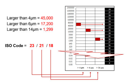
Particulate contamination in a system is often reports as an ISO (International Organization for Standardization) Code. The objective of the ISO Standards 4406:1999 is to classify quantity of particle contaminants in hydraulic fluids by particle size. Particle counts are determined cumulatively, i.e. > 4 μm, > 6 μm and > 14 μm, and coded for easy comparison. The following table explains how the ISO code is determined for a particular fluid sample:
Sources of Contamination
The source for particulate contamination is often found to be the hydraulic reservoir.
Often the reservoir is filled with fluid without first being cleaned. Dirt can be added during maintenance cycles, the tank is open to the environment and missing or has low quality air breathers installed on the tank.
New fluid coming into the plant (in a drum, tote or truck) is generally dirtier than what a system, and specific components in the system, would require for proper performance and/or adequate life expectancy. Over time, pipe scale/rust, pump wear and dirt on rods/cylinders can add contamination to the fluid.
Particulate contaminants circulating in fluid power systems cause surface degradation through general mechanical wear (abrasion, erosion, and surface fatigue). This wear causes increasing numbers of particles to be formed, the result being that wear increases if the “chain reaction of wear” is not properly contained (by reducing contamination). Gaps grow larger, leakage oil flows increase in size and operating efficiency (e.g. of pumps, cylinders) decreases.
Water contamination in the hydraulic systems can be caused by moisture from ambient air, leakage of cooling systems or process water, leakage of seals and chemical processes such as combustion, oxidation and neutralization. As more water enters the fluid, the fluid will develop a haze to milky/stratified appearance when fully saturated.
Dissolved Water is responsible for:
- Faster oil oxidation: Accelerates this form of oil degradation, leads to oil acidity, thickening, varnishes, sludge & resins
- Reduced Fatigue life: Propagation of fatigue cracks in metals
- Demolition of Ester-based fluids and additives: Reacting with esters – hydrolysis, results in formation of acids, gels, and loss of additives
Free Water causes:
- Corrosion: Corrosion pits, rough surfaces and release of abrasive flakes into the fluid
- Microbial colonization / Bacteria: Odors, acids, slime, and health problems
- Loss of lubricity: High friction, wear and seizure of components due to additive reduction/depletion seen with high water content
- Additive depletion: Free water retains polar additives
Design issues in the hydraulic system can contribute to air/gases in hydraulic fluids. If the return line is above the fluid level in the tank, air can be mixed into the fluid. Incorrect motor speeds, unprimed pumps, suction lines too small, suction lifts too high and blocked inlets are among other reasons for air contamination over time.
Air effects:
- Oil oxidation: Mostly oxygen reacts with oil resulting in premature degradation (oil aging)
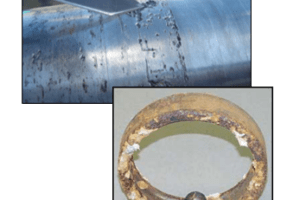
- Varnish formation – lacquer like deposits as shown in photo (oil aging)
- Cavitation: Formation and collapse of gaseous oil cavities causes decrease in pump efficiency and damage to pumps
- Micro-Diesel-Effect – Air bubble implosion generating high heat which “burns” the oil surrounding the air bubble
- Change of viscosity
Hydraulic component clearances are critical and require strategic filtration designs to remove damaging particles. In hydraulic systems, 70 to 90% of wear and failure is contamination related. Only 10 to 30% can be traced back to misuse, defects or age. Contamination cannot be stopped, only slowed down!
System efficiency can drop by up to 20% before an operator even detects a problem, such as cylinder drift, jerky steering, erratic operation or slower performance. Overall, contamination results in shorter service intervals, higher operating costs and lost productivity.