


Fluid Contamination Control: What You Need To Know


Did you know that over 70% of all hydraulic system failures are caused by contaminants in the fluid?

Ingression of solid particulates, liquid, and air bubbles are constant threats for hydraulic equipment. Without proper filtration, these contaminants can impact your vital equipment in many ways:

  • Reduced hydraulic system efficiency
  • Reduced lifespan of machine components
  • Damage to cylinders, pumps, motors, seals, and other important system components.
  • Expensive repairs and machine downtime
  • Catastrophic failure of hydraulic equipment while in operation

Hydraulic filtration is the key to controlling contamination and protecting your equipment.

Schroeder Industries is a global provider of high-performance, high-efficiency filtration solutions, including our range of onboard hydraulic filters. Our experts can work with you and your team to determine a treatment plan for your hydraulic fluid and guide you towards the optimal products and solutions for your filtration needs.


Hydraulic & Lube Filtration Solutions from Schroeder Industries

Schroeder Industries is backed by over 75 years of manufacturing experience. Our hydraulic filters are made in America and engineered to excel, with comprehensive options for virtually any application:
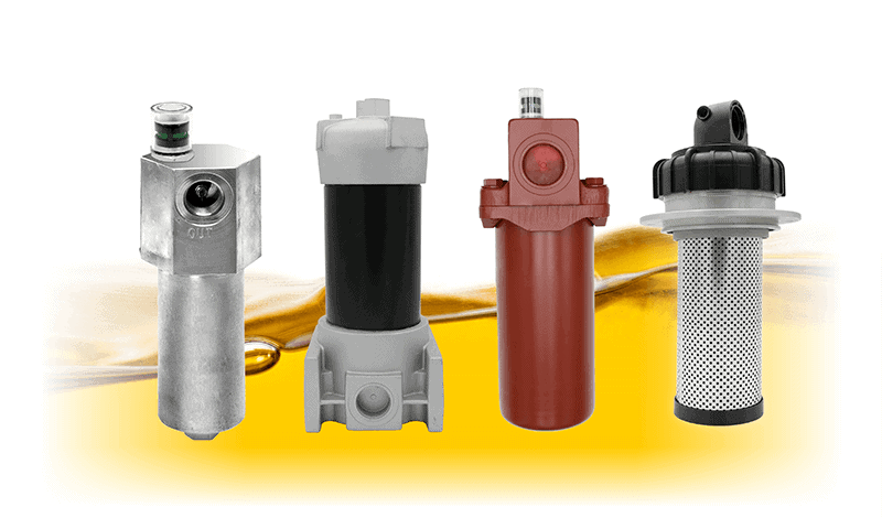
  • Top / Base Ported Filtration
  • Manifold Mounted Filter Kits
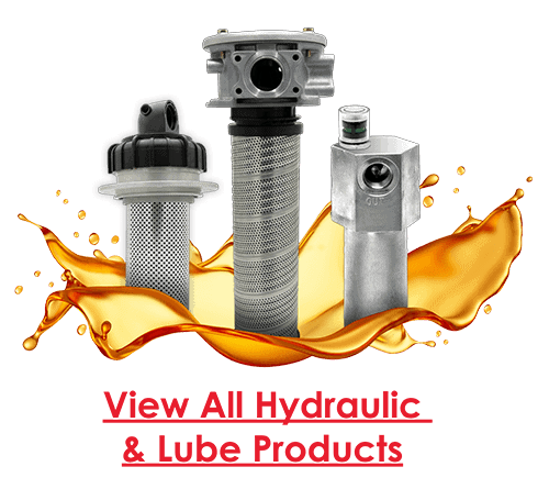
  • Hydraulic Tank Filters (In–Tank/Tank Top)
  • Servo Protection Filters
  • Tank-Mounted Suction Filters
  • Next Generation In-Tank Deaerating Filters
  • And more!


Featured Hydraulic & Lube Filters


Combined with our range of premium filter elements and other hydraulic accessories, our filters are engineered for excellence in removing contamination. Here are just a handful of Schroeder’s industry-leading hydraulic filters:
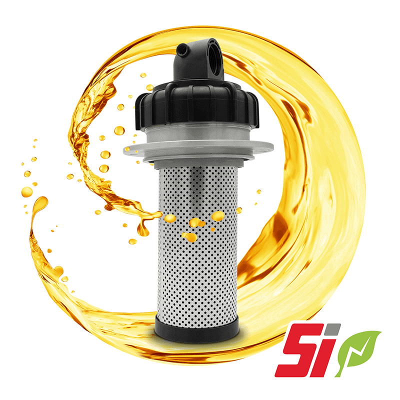

Air Fusion Technology (AFT): Engineered for Optimal De-Aeration

The cutting edge in de-aerating filtration, engineered in all aspects for enhanced air removal!

Flow Rating:40 gpm (151 L/min)
Max. Operating Pressure:100 psi (7 bar)
Min. Yield Pressure:350 psi (24 bar)
Rated Fatigue Pressure:100 psi (7 bar)
Temp. Range:-20°F to 225°F (-29°C to 107°C)
Bypass Setting:Cracking: 30 psi (2 bar)
Full Flow: 45 psi (3 bar)
Element Change Clearance:4LK = 5.28” [134mm]
8LK = 8.62” [219mm]
12LK = 11.96” [304mm]
16LK = 15.30” [389mm]
Element Case:12 elements


GPT: Advanced Cold Start Protection with a Sustainable Twist
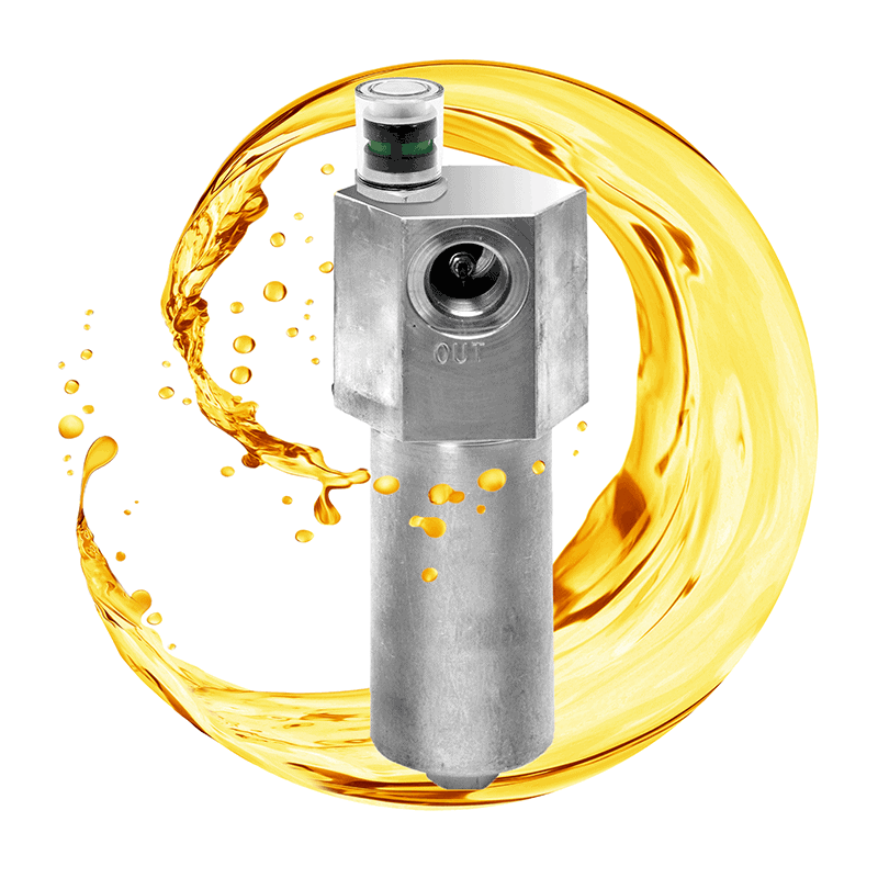
Built with a unique bypass location for cold start protection and a reusable diverter cap that reduces waste!

Flow Rating:Up to 175 GPM (662 L/min) FOR 150 SUS (32 cSt) Fluids
Max. Operating Pressure:150 PSI (10.3 bar)
Min. Yield Pressure:Consult Factory
Rated Fatigue Pressure:89 psi (6 bar)
Temp. Range:-20 F to 225 F (-29 C to 107 C)
Bypass Setting:Cracking: 35 PSI (2.4 bar)
Ported Head and Cap:Die Cast Aluminum
Weight:7 LBS. (3.18 kg)
Element Change Clearance:20.0″ (508 mm)


NF30: Rock-Solid Filtration in High Pressure Applications
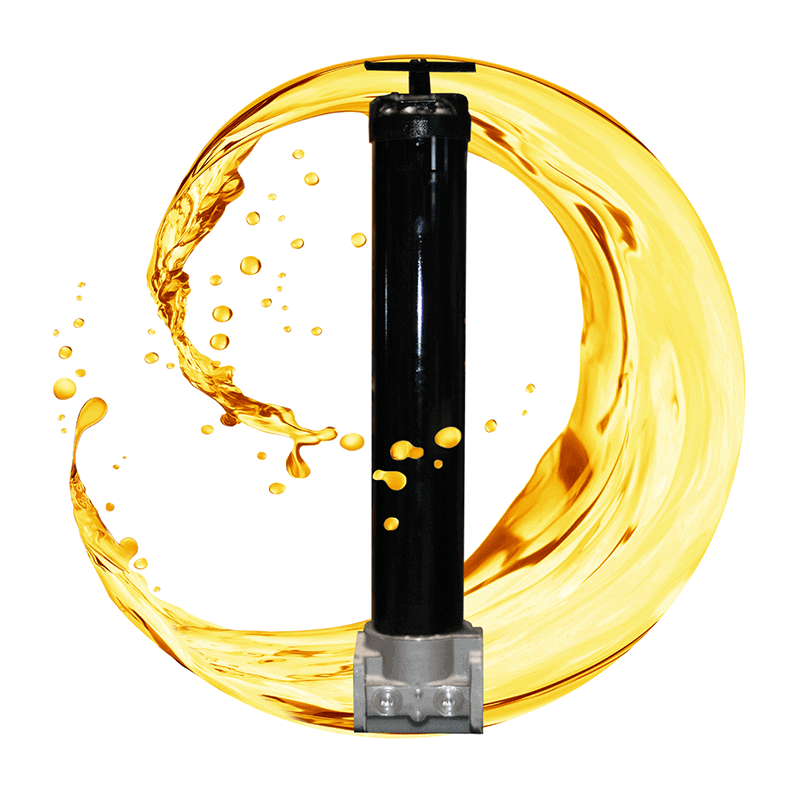
The all-aluminum NF30 filter design excels in high-pressure applications and offers a Lock & Key Quality Protection option!

Flow Rating:Up to 20 gpm (75 L/min) for 150 SUS (32 cSt) fluids
Max. Operating Pressure:3,000 psi (210 bar)
Min. Yield Pressure:10,000 psi (690 bar), per NFPA T2.6.1
Rated Fatigue Pressure:2,400 psi (165 bar), per NFPA T2.6.1
Temp. Range:-20°F to 225°F (-29°C to 107°C)
Bypass Setting:Cracking: 40 psi (2.8 bar)
Full Flow: 85 psi (5.9 bar)
Non-bypassing model has a blocked bypass
Porting Head:Aluminum
Element Case:Aluminum
Weight of NF30-1N:3.4 lbs. (1.5 kg)
Weight of NF30-1NN:4.4 lbs. (2.0 kg)
Element Change Clearance:4.50″ (115 mm)

QF5: A Medium Pressure Workhorse with Straightforward Maintenance

The QF5 filter series allows straightforward element change outs from the top, minimizing oil spillage, and can be modified for coreless elements!

Flow Rating:Up to 300 gpm (1135 L/min) for 150 SUS (32 cSt) fluids
Max. Operating Pressure:500 psi (35 bar)
Min. Yield Pressure:2,500 psi (172 bar), per NFPA T2.6.1-R1-2005
Rated Fatigue Pressure:Contact Factory
Temp. Range:-20°F to 225°F (-29°C to 107°C)
Bypass Setting:Cracking: 30 psi (2.1 bar)
Full Flow: 55 psi (3.8 bar)
Porting Base:Cast Aluminum
Element Case:Steel
Cap:Ductile Iron
Weight of QF516:85 lbs. (39 kg)
Weight of QF539:120 lbs. (55 kg)
Element Change Clearance:16Q: 12″ (205 mm)
39Q: 33.8″ (859 mm)

View QF5 in Catalog

Case Studies: Hydraulic & Lube Filtration


Don’t just take Schroeder’s word on the quality of our products. Here are just a few success stories highlighting how hydraulic filters from Schroeder Industries’ Hydraulic and Lube group saved our customers money, downtime, hassle and more!
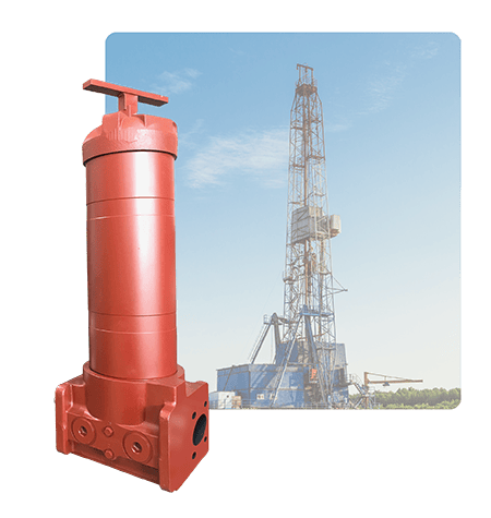


When a Frac Drilling OEM in West Texas was facing delivery delays and contamination issues with their filters, the experts at Schroeder stepped in to provide a cost-effective, high-performance filtration solution.

Schroeder Industries upgraded the OEM’s system with the QF5i, featuring an innovative magnetic filter rod.

The QF5i’s magnetic filter rod increases capture of metallic particles and improves the overall dirt holding capacity of the new filter elements by preventing ferrous particles from reaching the element.

The increased dirt holding capacity and overall longer life expectancy of the filter elements allowed the OEM to save substantially on the cost of replacement elements alone.

Here’s how this OEM benefited from this Schroeder Solution!



Dirt Holding Capacity:

+73% (40 µm)
+254% (25 µm)


Element Life Expectancy:

+40% Versus
Competitor


Element Cost Savings:

40% – 60%
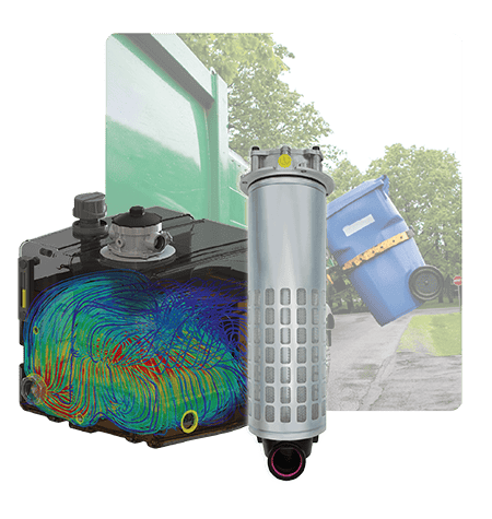


An OEM manufacturing a variety of hydraulic refuse trucks sought ways to improve the design and efficiency of their side loader model.

When Schroeder Industries performed a Tank Optimization analysis, our experts saw clear opportunities for tank performance improvements and downsizing.

By combining next generation BRT in-tank filtration and an optimized rotomolded reservoir design, the customer was able to downsize their reservoir substantially!

Here’s how this OEM benefited from this Schroeder Solution!



Reservoir Reduction:

-19 Gallons
-335lbs


Initial Cost Savings:

$380 USD per Unit


CO2 Reduction:

-450lbs CO2 per Unit


You could be Schroeder’s next success story!


Tell us about your application and the challenges you face, and our experts can help find the filtration solution that fits your needs.


Request a Quote


Request for Quote

  • Which products are you interested in?
  • Max. file size: 256 MB.

Hydraulic Filtration: Frequently Asked Questions


Contamination Control Principles

An ISO Code is a numerical code used to quantify the amount of solid contamination in operating fluids, including hydraulic oils and diesel fuel. Each of the three numbers in an ISO Code represents an amount of contamination within a certain size range. The higher the numbers are in the ISO Code, the more solid contamination is present. 

An ISO Target is, basically, the ISO Code that represents the desired cleanliness for a given machine or hydraulic system. Manufacturer guidelines usually include a minimum ISO Target to ensure that a machine meets its operational lifespan and expected maintenance schedule. 

Schroeder Industries breaks down the significance of ISO Codes and the importance of meeting ISO Targets in this video:


All three are harmful, but solid particles (dirt and wear metals) are responsible for the majority of hydraulic component failures. Particles in the 5-15 micron range are especially damaging because they match the clearances inside pumps and valves. Water accelerates oxidation, reduces lubricity, promotes corrosion, and can lead to sludge and varnish formation.  

Rule of Thumb: Control solid contamination first, then water contamination. 


You should always at least meet the minimum ISO Target for your hydraulic system at all times. This ensures that you are protecting your system and its components from the damaging effects of contamination. While it is generally not possible to remove all contaminants, the cleaner your oil, the better! 


The best way to prevent contamination when adding new oil is by testing and filtering any new fluids prior to filling your equipment. Before adding any new fluid, it’s important to ensure that the ISO Code and saturation levels of the fluid meet the cleanliness targets for your equipment. When filling, consider using portable filtration units or mobile filtration carts that can filter fluid as it is added to your system. 

Additionally, you should ensure that any hoses used in the filling process are clean to avoid cross-contamination. Open reservoir caps only when necessary and close them promptly when filling is complete to minimize exposure to ambient contamination.  


No, you should never assume that new hydraulic oil is clean enough to add directly to your system without filtration. ‘New’ hydraulic oil can be as much as 32x dirtier than the minimum cleanliness target of a typical, modern hydraulic system.

Depending on the manufacturer and methods of storage, transport, and delivery, even new oil can be loaded with solid contamination.  


Depending on what cleanliness parameters you are looking for, and the type of equipment you are using, there are several ways to monitor oil cleanliness.

  • Laboratory Testing: Laboratory fluid testing is helpful for detecting contamination when on-site sensors are not available, or when seeking information on fluid characteristics which can’t be measured with typical sensors (such as varnish or varnish precursors). Because lab testing does not provide fluid condition data in real time, it is recommended that sensors are used on-site to supplement your fluid monitoring.

  • In-Line Sensors: In-line contamination sensors are built into the hydraulic system of an individual machine and provide real-time updates on solid contamination and fluid saturation for that specific system. In-line sensors are excellent for continuously monitoring individual equipment assets. Many modern sensors include mobile connectivity, allowing operators to check on fluid condition in their equipment from mobile devices and smart phones.

  • Portable Sensors: Portable sensors can be used to measure the cleanliness of multiple machines and can even accompany equipment fleets in the field. Unlike in-line sensors, portable contamination sensors include built-in pumps that allow them to travel between different equipment assets and test equipment even when it is powered down.

Built in contamination is contamination that occurs during the process of manufacturing, assembling, and testing a system or machine prior to final delivery. This contamination is a common cause of premature machine wear and claims within warranty. Built in contamination may come in the form of:

  • Machining debris, such as metal shavings or plastic fragments

  • Ambient contamination, including dust and debris in the assembly area and parts storage, or even humidity in the air

  • Contaminated first-fill operating fluids (hydraulic fluid, diesel fuel, etc.)

Schroeder Industries explains the common causes and consequences of built in contamination in the following video:


Preventing built in contamination means controlling contamination in your assembly environments, part storage, and bulk fluid storage environments as much as possible.

  • Clean Storage and Handling Practices: Avoid exposing stored parts to ambient dust and humidity, or to cross-contamination during transfer, assembly, and handling.  

  • Component Testing: To ensure that your contamination control practices are working, manufacturers should complete regular component testing using either dedicated component testing equipment, or through a testing service. Component testing can identify contamination and give clues about its source, detecting weaknesses in cleanliness practices.

  • Maintain Clean Assembly Area: Ensure that areas where component or system assembly occur are as free from dust, humidity, and other environmental contaminants as possible.

  • Filter New Fluids: New fluid doesn’t mean clean fluid. Before filling hydraulic and fuel tanks for equipment testing, ensure that any operating fluids have been filtered to the minimum cleanliness standard for your system.

Schroeder Industries explains the common causes and consequences of built in contamination in the following video:


Hydraulic Filter Selection

The correct micron rating depends on a few different factors:

  • Most sensitive component
  • Desired ISO cleanliness target
  • Flow rate and pressure conditions

Typical starting points for micron ratings for various filter positions are:

Application:Typical Micron Rating:
Suction Protection75-150 µm screen/separator
Pressure Line Filter3-10 µm
Return Line Filter5-10 µm
Kidney Loop/Offline Filter3-5 µm

You should always choose filtration based on the cleanliness level required by the system’s most sensitive component.


Controlling contamination is critical, but that doesn’t necessarily mean that finer hydraulic filtration is always better.

A very fine filter can increase the system pressure drop, reach dirt holding capacity faster, require more frequent element changes, create cold-start issues, and increase the cost unnecessarily.

The goal in hydraulic filtration is to achieve the required cleanliness level while maintaining acceptable differential pressure and dirt-holding capacity.


Use OEM cleanliness requirements, ISO cleanliness targets provided by the manufacturer, and beta-rated filter performance. (Note: Nominal filtration ratings alone should not be relied on as indicators of performance!)

If fluid analysis consistently meets the cleanliness target required by the most sensitive component, the filter is doing its job.


When a filter is advertised as a ‘5 micron element,’ etc, that is known as its nominal rating. A filter element earns a nominal rating by meeting the minimum beta efficiency (or capture rate) for that particle size, but the minimum efficiency can be as low as 50% depending on the type of filter element.

Absolute filter ratings, on the other hand, are based on actual performance testing and efficiency according to ISO standards. A filter’s absolute rating is a more accurate measurement of its efficiency compared to a nominal rating.

Check out the following video for a detailed description of the differences between nominal and absolute filter ratings:


While the number and type of filters are often application-dependent, many modern systems benefit from a combination of pressure, return, and offline filtration.

Suction Filtration:

  • Protects the pump from large debris
  • Reduces contamination load on finer downstream filtration
  • Avoid using fine media in a suction filter, as cavitation may occur

Pressure-Line Filtration

  • Considered the best protection for expensive pumps and valves
  • Micron rating for pressure line filters typically ranges from 3-10 microns

Return Line Filtration

  • Captures contamination before fluid returns to the reservoir
  • Specialized deaerating return line filters can also minimize air contamination
  • Common and cost-effective

Offline (Kidney Loop) Filtration

  • Offline filters provide cleaning independent of machine operation
  • Often the most effective filtration method
  • Micron range for offline filters usually ranges from 3-5 microns


Hydraulic Filter Maintenance

Change filters based off of differential pressure indication, oil cleanliness data, contamination level, and operating severity.

Fixed-hour intervals are also a good recommendation, provided the intervals are based on proven data to ensure the system is properly being maintained in the interim.


Several tools are available to help determine the right time to change a filter element:

  • Differential pressure indicators detect when pressure drop occurs as an element reaches its maximum dirt holding capacity. When the differential pressure indicator is triggered, it is a clear signal that the element should be changed.
  • Electronic contamination monitors can track the fluid ISO Code in real time. When an electronic monitor shows an increase in contamination levels, it is likely a sign that the element is full, or is otherwise not functioning properly.
  • Scheduled oil analysis can also identify trends in contamination levels, and indicate whether the filter element is full or still functioning. While oil analysis does not provide immediate fluid condition results, lab testing can also be used to test for parameters than on-site monitors are unable to measure.

Changing the filter based on activated pressure indicators is generally the preferred method of determining filter maintenance versus operating hours.

A fixed interval of filter changes based on operating hours can be effective, but there is always a possibility that the filter element could be clogged prior to the scheduled change, or still have remaining capacity when the change is made.

By relying on a visible indicator that the element is full instead of changing automatically, equipment can be proactively protected in the event of high contamination loads, and element and maintenance-related expenses can be kept to a minimum.


General symptoms of a clogged filter include:

  • Increasing ISO Codes
  • Activated restriction indicators
  • Increased differential pressure
  • Bypass valve activation
  • Reduced system performance
  • Elevated oil temperatures
  • Slow actuator response

Generally, no, a hydraulic filter element cannot be cleaned and reused. Most modern hydraulic elements are designed as disposable components. Cleaning can potentially damage the media, reduce efficiency, create bypass paths, and shorten element life.

Always replace the element unless the manufacturer specifically approves cleaning and reuse.


Hydraulic System Performance Issues

Even if the oil looks clean, contamination can’t be ruled out as the cause of failure.

A visual inspection alone can’t detect fluid contamination. Many of the most damaging solid contaminants are smaller than can be seen by the human eye, requiring microscopes or specialized sensors to detect. Particulates smaller than 10 microns, far below the limit of human vision, can generate more wear than large, visible particles.

When failures occur, fluid testing in a laboratory setting is recommended to determine the amount and type of contaminants affecting your system. Regular oil analysis is recommended to ensure fluid cleanliness and detect spikes in contamination levels before they can become critical.


New oil does not mean it is clean oil, so it is possible that the fluid was contaminated before being added to the system

Besides new oil being brought into the system, hydraulic oil can get dirty from poor reservoir breathers, inadequate filtration, worn seals in hydraulic equipment, internal component wear, and improper maintenance practices.


Yes, a heavily restricted filter can reduce the flow, increase the pressure drop, cause bypass operation, and reduce actuator speeds.


Probable causes are high levels of contamination, higher pressure losses, incorrect oil viscosity, pump wear, excessive leakage, and/or clogged filters.


Probable causes of overheating in a hydraulic system are restricted flow, higher pressure drops, aeration, internal leakage, improper fluid selection, and contamination-induced wear.


Troubleshooting

Early filter clogging is often a sign that there is significant contamination in the system:

  • External Contamination: The system may be experiencing higher than average contamination loads due to damaged seals, inadequate breathers, maintenance activities, reservoir openings, and other points of vulnerability.
  • Internal Wear: Rapid filter clogging can also be an early warning signs of deteriorating components. As components such as pumps, bearings, valves, and gears age, they introduce wear particles into the system.
  • Poor Fluid Cleanliness: Even if you are filling your system with ‘new’ oil, the oil may not be as clean as you think. Make sure that any new fluid added to the system has been filtered to the appropriate cleanliness target.
  • Rapid Oil Aging: As oil ages, it degrades into a sticky substance known as varnish, which can quickly foul filter elements. Overheating and air contamination are common drivers of oil aging and varnish formation.

If above-average contamination levels are not present, there may be issues with the filter’s sizing or its micron rating. If a filter is undersized or the micron rating is too fine for the application, the element will load faster, and require more frequent maintenance.


A filter’s bypass valve will open when maximum system back pressure is reached—that is, the pressure upstream of the filter is too high.

This can occur if the filter element has reached its capacity, if the filter is not properly rated for the system’s operating pressure, or if fluid viscosity has increased during cold temperatures (known as ‘cold start’ conditions).


Yes, the wrong filter could cause excessive restrictive on suction filters, causing cavitation. It could also lead to poor efficiency, allowing contamination through, structural failure or media collapse.


Metal particles are most often either built-in contamination left over from initial machining and assembly, or indicators of increased internal component wear.

If the machine is new or has recently been refurbished, it could be an indicator that metallic debris was introduced to the system during the initial manufacturing process or reassembly.

If the metal particles have appeared over time, they are most likely an indicator of component degradation. Oil testing using ICP Elemental Analysis can help identify the molecular makeup of the metals and give clues as to which components may be failing, as certain components are often made with different metals or alloys. As components degrade, the wear particles can further accelerate damage throughout the system. Locating and controlling the source of metal particulate contamination quickly is essential.


Immediately:

  • Shut down the equipment if it is safe to do so.
  • Inspect bypass and differential pressure indicators.
  • Replace the element.
  • Investigate contamination sources.
  • Consider oil analysis.

A collapse indication suggests the element may no longer be protecting the system.


Cost and Reliability

In most cases, yes. A higher-efficiency filter has numerous benefits such as:

  • Longer Component Life
  • Reduced Downtime
  • Extended Fluid Life
  • Improved Machine Reliability
  • Reduced Repair Costs

Filtration is often one of the lowest-cost reliability improvements available.


While results vary by application, contamination-related failures are one of the largest causes of hydraulic downtime. Reducing contamination can significantly improve uptime, equipment reliability, and service life.


Yes, better filtration can extend hydraulic oil life. While hydraulic and lubricating oils don’t last forever even under ideal circumstances, contamination accelerates the aging process of the oil and can significantly reduce its usable life. In some applications, years can be added to fluid life by implementing effective filtration.


Filtration improves equipment reliability by removing contamination and preserving the operating efficiency of system components longer. Contamination is known to degrade oil quality, cause sticking valves, wear out gears and other components, and generally cause damage which reduces system efficiency over time. Eventually, if contamination is not controlled, machine failure is likely. Sudden, disruptive machine failures are often the result of high contamination levels.

Effective filtration is proven to reduce equipment downtime by allowing components to function at their full potential and meet (or even exceed) their expected operating lifespan.


While the actual dollar amounts lost due to contamination vary depending on the scale of an operation, there are a few general ways that contamination cuts into overall profits:

  • Maintenance Costs. As contamination increases wear and damage throughout a hydraulic or fuel system, components will fail to meet their operational lifespan and need replaced more frequently. The cost of new components and repair services are a significant source of contamination-related expenses.
  • Fluid Recycling and Replacement. While no oil lasts forever, contamination is proven to dramatically shorten the usable life of hydraulic and lubricating oils. When fluid becomes contaminated to critical levels, operations may need to pay for fluid recycling and disposal services. On top of that, the operation must purchase new fluid to replace what is lost.
  • Equipment Downtime & Lost Productivity. Equipment that fails suddenly or requires more frequent maintenance spends less time doing productive work. Depending on the application, even a small amount of unexpected machine downtime can translate to many thousands of dollars in delayed product, lost business, and reputational harm.


Training and Best Practices

  • Clean the surrounding area to minimize contamination during the filter change
  • Use the correct replacement element according to your machine and filter specifications
  • Verify seals and O-rings are intact and of the correct material
  • Inspect the used element removed for unusual debris or damage, such as metallic particles and scorch marks
  • Pre-fill only when recommended by OEM
  • Record change date and hours
  • Verify no leaks after startup
  • Consider oil analysis if abnormal contamination is found

Contamination during maintenance is typically caused by contamination in any newly installed parts, contamination in the maintenance environment, and contamination in new operating fluids. Here are some ways to maintain system cleanliness during maintenance:

  • Ensure replacement component cleanliness through component testing and clean handling practices.
  • Avoid cross-contamination from dirty tools or a dirty maintenance environment.
  • Minimize exposure of components, reservoir openings, and filter housing interiors to ambient contamination.
  • Test and filter all fluids before adding them to the system. ‘New’ hydraulic fluids often exceed system cleanliness requirements, and fluids kept in storage may accumulate contamination over time even under the best circumstances.


Modern systems often use multiple filters in different locations to ensure cleanliness. Best-practice locations icnlude:

  • Pressure-line filtration (maximum component protection)
  • Return-line filtration (captures contamination from the machine)
  • Kidney-loop filtration (continuous cleanup)
  • Reservoir breathers (prevent ingression)
  • Suction protection where appropriate


Manufacturer guidelines typically include a minimum ISO Target for each type of machine or hydraulic system. This target is designed to ensure that the machine and its components meet their expected operational lifespan. An ISO Code of 16/14/11 is a common ISO Target for modern hydraulic systems, but operators should consult their manufacturer’s operating guidelines to ensure they are meeting the target for that specific system.

However, it may be possible to establish even cleaner fluid goals that help equipment and components last longer. Experts in hydraulic filtration can help you find out if achieving cleaner fluid while maintaining peak system efficiency is possible for your specific machine and application.

To learn more about the importance of meeting minimum ISO Targets, check out this video from Schroeder Industries:


Fluid is specified by the customer’s application, but a good practice is to ensure that the proper viscosity grade is chosen for the desired operating conditions. Incorrect fluid selection can reduce efficiency and shorten component life.


Mixing oils is generally not recommended as it can alter additive chemistry, affect seal compatibility, reduce overall fluid life, and cause unexpected performance issues. Always verify fluid compatibilities before mixing.